ReconFlexTM cameras
Many aspects of the scTDC SDK work very similar for ReconFlexTM cameras compared to the TDC and DLD products by Surface Concept GmbH. Initialization of the device, the general concept of pipes for receiving data, the starting of measurements, and deinitialization of the device work the same way. However, cameras offer a number of configuration options and operation modes which are controlled by camera-specific API functions.
Configuring camera parameters
Setting exposure (per frame) and number of frames for measurements
For ReconFlexTM cameras, measurements are not characterized by a single duration value. They can comprise a configurable number of camera frames, which means that the camera sensor may perform multiple exposures and accordingly be read out multiple times during a single measurement. Within one measurement, all camera frames are taken with the same exposure. The total duration of a measurement is still somewhat complex to estimate. In the simplest case, it is roughly the product of number of frames times the exposure per frame. However, if the exposure per frame is chosen very small and the hypothetical gap-less frame sequence exceeds the maximum frame rate of the camera, the firmware will instead drive the sequence of frame exposures with time gaps between the frames to the effect that the maximum possible frame rate is reached.
As a consequence, when calling sc_tdc_start_measure2(), the argument
for the exposure time is ignored. The exposure time and number of frames
for the camera is instead controlled by calling sc_tdc_cam_set_exposure()
before starting the measurement, thereby implicitly defining the total
duration of a measurement.
Selecting raw image mode or blob mode
A central aspect concerning configuration is whether the camera is set up to deliver raw images (as recorded by the sensor) or blob data (where intensity peaks in the raw image are recognized by the camera firmware and turned into a list of coordinates that is sent to the PC).
When the application initializes the camera, the selected mode depends
on entries in the ini file (BlobDifMinTop and BlobDifMinBottom
in the [CMOS] section). To change the mode, make sure, the camera
is initialized and not currently in a measurement.
To select the raw image mode, create a variable of type
sc_BlobParameters, fill its contents as shown in the code below and callsc_tdc_set_blob_parameters():// assumes that an 'int dev_desc' variable contains the // device descriptor of an initialized camera sc_BlobParameters p; p.unbinning = 1; p.dif_min_top = 0; p.dif_min_bottom = 0; p.z_scale_factor = 1.0; int ret = sc_tdc_set_blob_parameters(dev_desc, &p); if (ret < 0) { // an error occurred }
To select blob mode, do the same with values for
p.dif_min_topandp.dif_min_bottomthat are greater than 0:sc_BlobParameters p; p.unbinning = 1; p.dif_min_top = 2; p.dif_min_bottom = 5; p.z_scale_factor = 1.0; int ret = sc_tdc_set_blob_parameters(dev_desc, &p); if (ret < 0) { // an error occurred }
In these examples, p.dif_min_top and p.dif_min_bottom
correspond to the ini file entries BlobDifMinTop and
BlobDifMinBottom, respectively. Their allowed values range from
1 to 63 for blob mode, whereas the special value 0 turns blob mode off.
The lower these values, the more blobs are found. For more details, see
Blob recognition criteria.
The blob recognition criteria also refer to BlobRelax (ini file
parameter). After initialization of the camera, this parameter can be
changed by application code, as follows (here, the parameter is set to
0):
// assume that dev_desc is a variable containing the device descriptor
sc_tdc_cam_set_parameter(dev_desc, "BlobRelax", "0");
The sc_tdc_cam_set_parameter() expects the parameter value in a
string form (char*).
Blob recognition criteria
For blob recognition, the firmware of the camera scans through the raw image and evaluates a 5x5 square of intensities at every position. A set of conditions is checked to decide whether there is a blob at the center of the currently considered 5x5 square, where two rings of intensities are distinguished as shown in the following image:
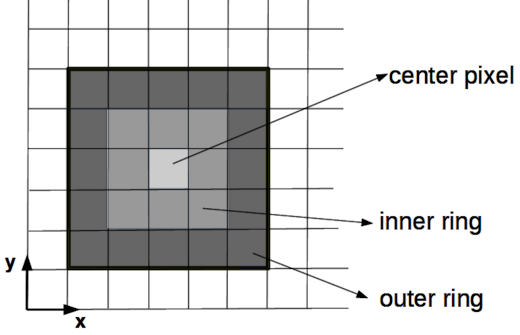
Condition 1: The grey scale value of the central pixel must be bigger than or equal to all 8 pixels of the inner ring.
Condition 2: Each of the pixels in the inner ring must have grey scale values bigger than or equal to their neighbours that are part of the outer ring. This condition can be relaxed via the parameter
BlobRelaxas follows:BlobRelax = 0: original behaviour, no relaxationBlobRelax = 1: no comparison with the corners in the outer ringBlobRelax = 2: only the 4 pixels in the outer ring lying on the horizontal and vertical axes are comparedBlobRelax = 3: condition 2 is not probed at all
Condition 3: The grey scale value of the center pixel exceeds the average of the grey scale values of the inner ring by a difference at least as high as
BlobDifMinTop(ini file parameter), or fielddif_min_topinsc_BlobParameters.Condition 4: The average of the grey scale values of the inner ring exceeds the average of the outer ring by a difference at least as high as
BlobDifMinBottom(ini file parameter), or fielddif_min_bottominsc_BlobParameters.
Setting a region of interest (ROI) on the hardware level
When recording images or blob data with a camera, not all of the sensor area may be of interest. Reducing the active area of the sensor enables access to higher frame rates and reduces data transfer (per recorded camera frame) from the camera to the PC. The reduced data transfer has the largest impact when the camera is operated in the raw image mode. The increased frame rates are enabled when reducing the number of lines (ROI height).
After initialization of the device, the ROI defaults to a setting
defined by the ini file parameters x_min, x_max, y_min,
y_max in the [CMOS] section.
To modify the region of interest, make sure the device is initialized
and not currently in a measurement, then call sc_tdc_cam_set_roi().
The region of interest may not always be set to exactly the boundaries
specified in sc_tdc_cam_set_roi() – for example, if the request
exceeded the available sensor area or due to technical limitations that
prevent pixel-perfect selection. To query the actual active ROI after
your set request, use sc_tdc_cam_get_roi().
Selecting the dynamics range of intensities in raw images
The sensor of the camera can be configured to enable maximum intensities per pixel of either 255 (8-bit) or 4095 (12-bit). The 12-bit mode allows for longer exposures without saturating pixels at the maximum intensity. The 8-bit mode enables higher frame rates.
Note
Even in blob mode, the dynamics range has an impact, since the blob data is based on localizing intensity peaks in raw images (which happens in the camera). Even if you are not interested in the raw images, accurate blob positions require that the raw images are not overexposed.
The choice between 8-bit mode and 12-bit mode is fixed during
initialization stage and cannot be modified afterwards. By default,
the ini file parameters BitMode and BitTransferMode define
which mode is active. To modify this choice from code without
modification of the ini file, you can use the override registry
interface:
int ovr = sc_tdc_overrides_create();
sc_tdc_overrides_add_entry(ovr, "CMOS", "BitMode", "8");
sc_tdc_overrides_add_entry(ovr, "CMOS", "BitTransferMode", "8");
sc_tdc_overrides_add_entry(ovr, "CMOS", "BitShift", "0");
// or: sc_tdc_overrides_add_entry(ovr, "CMOS", "BitMode", "12");
//     sc_tdc_overrides_add_entry(ovr, "CMOS", "BitTransferMode", "12");
//     sc_tdc_overrides_add_entry(ovr, "CMOS", "BitShift", "0");
int dd = sc_tdc_init_inifile_override("tdc_gpx3.ini", ovr);
sc_tdc_overrides_close(ovr);
// if dd >= 0, the camera is now initialized with the selected bit mode.
A mixed mode exists, where the sensor is configured for 12-bit mode
but the data transferred to the PC is cropped to 8-bit intensity
values. This can be done by dividing the sensor intensities by
24 = 16, which maps the maximum possible intensities from
12-bit mode to 8-bit mode and reduces the resolution in graylevels.
This choice corresponds to parameter values BitMode = 12,
BitTransferMode = 8, BitShift = 4. This setting enables the same
length of exposures as in 12-bit mode but reduces data transfer to the
PC.
Alternatively, the sensor intensity can be divided by a lower power of 2,
if the expected intensity values are low enough. This is achieved by
BitShift values less than 4.
Receiving Data
DLD_IMAGE_XY pipe versus PIPE_CAM_FRAMES pipe
The image pipe DLD_IMAGE_XY, originally aimed at
delay-line detectors, can be used to deliver raw sensor images or images
constructed from the list of blobs. This functionality is offered as a
backwards compatible way for existing DLD applications that have been using
this pipe before. Since DLD image pipes deliver only one
data set per measurement, in general they add the intensities from multiple
camera frames, or filter a subset of the camera frames.
The configuration parameters of these image pipes do not contain a field
for camera frames. Instead the time-related parameters are reinterpreted as
parameters relating to the frame index. If the camera is configured to record
5 frames in a single measurement, we label the frames by indices 0, 1, 2, 3, 4.
Setting the roi.offset.time = 1 and the roi.size.time = 2 would mean
that the intensities in the frames with indices 1 and 2 are added up and
the resulting image is delivered at the end of the measurement. The remaining
camera frames 0, 3, 4 are discarded in that case.
The image pipe DLD_IMAGE_XY introduces a considerable computational overhead, when used for raw images, since this pipe needs to implement the behaviour suggested by its configuration parameters — such as imposing a region of interest in addition to the region of interest defined at the hardware level of the camera sensor. A more performant interface for receiving raw image data is the PIPE_CAM_FRAMES pipe. This pipe delivers image data of individual camera frames while they are being reconstructed from the hardware data stream sent to the PC. Additionally, this pipe delivers meta information for every camera frame. Opening and reading of this pipe has very little impact on computational effort.
User callbacks interface versus PIPE_CAM_BLOBS pipe
The user callbacks interface, originally aimed
at delay-line detectors, can be used to deliver lists of blob data for
example in existing applications which already integrated this interface.
Here, the sc_DldEvent is reinterpreted as a blob event. The fields
dif1 and dif2 contain the blob coordinate. The field adc contains
the digitized value of the analog voltage on the ADC hardware input which
is updated once per frame. The field sum contains the index of the camera
frame. The field time_tag contains the time stamp of the camera frame.
Other fields are without meaning.
The user callbacks interface while not being the most efficient way of
transporting blob data, offers decent performance. Its limitation is the
data type of the blob coordinates which is an unsigned integer type.
ReconFlexTM cameras of the model variant ‘S’ offer precision of
blob coordinates beyond the pixel grid of the camera sensor by evaluating
a blob position from its intensity distribution in the raw image. The most
natural way to express the blob coordinates is therefore by using
floating-point number types. With the user callbacks interface, the loss of
precision can be worked around by configuring an upscaling option (see
sc_BlobParameters and sc_tdc_set_blob_parameters()). In that
case, the floating-point blob coordinates are multiplied by the upscaling
factor before being stored in the sc_DldEvent structure.
The replacement for the user callbacks interface is the PIPE_CAM_BLOBS pipe.
Combining PIPE_CAM_FRAMES and PIPE_CAM_BLOBS pipe
The above-mentioned pipe types are designed such that they can be read
in a synchronized fashion. They both deliver one data set per camera
frame at the moment that the hardware protocol stream, internally
decoded by the scTDC library, has reached the end of a camera frame.
Consequently, the calls to sc_pipe_read2() for these two pipes can
be put in sequence into a loop, and as long as both pipes are being
read the same number of times, their returned data belongs to the same
camera frame. This kind of reading pattern is necessary to associate
blob data with particular camera frames and measurements, as well as the
meta data associated with each frame, such as ADC values and frame time
stamps.
The example code Camera pipes for frame meta info, raw images and blobs reads both pipe types
in a synchronized way.