From standard product to special application.
FOR SCIENTISTS &
COMPANIES.
FOR SCIENTISTS & COMPANIES.
From standard product to special application.


Single Anode Delayline Detectors
Microchannel plate based detector packages with a single, two dimensional meander structured delayline anode for position and time resolved detection of electrons, ions and photons with sub-ns time resolution and µm spatial resolution.
The delayline detectors are available with different active areas and are mounted on standard CF flanges with feedthroughs for signal transfer and HV supply.
They come as complete packages including analogue readout electronics, time-to-digital converter, software package and optional HV power supply for a plug and play installation and operation.

DLD8080 Detector Packages
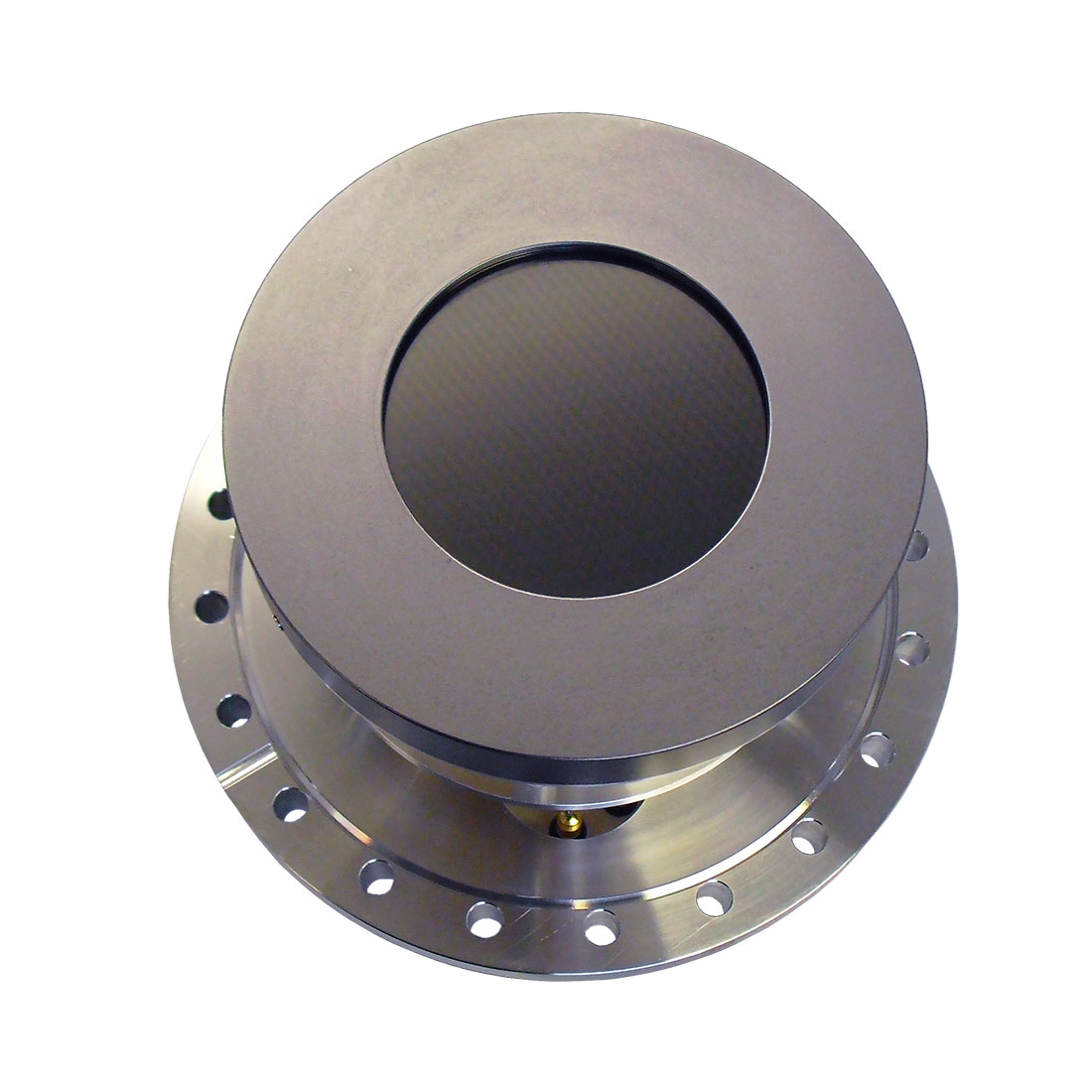
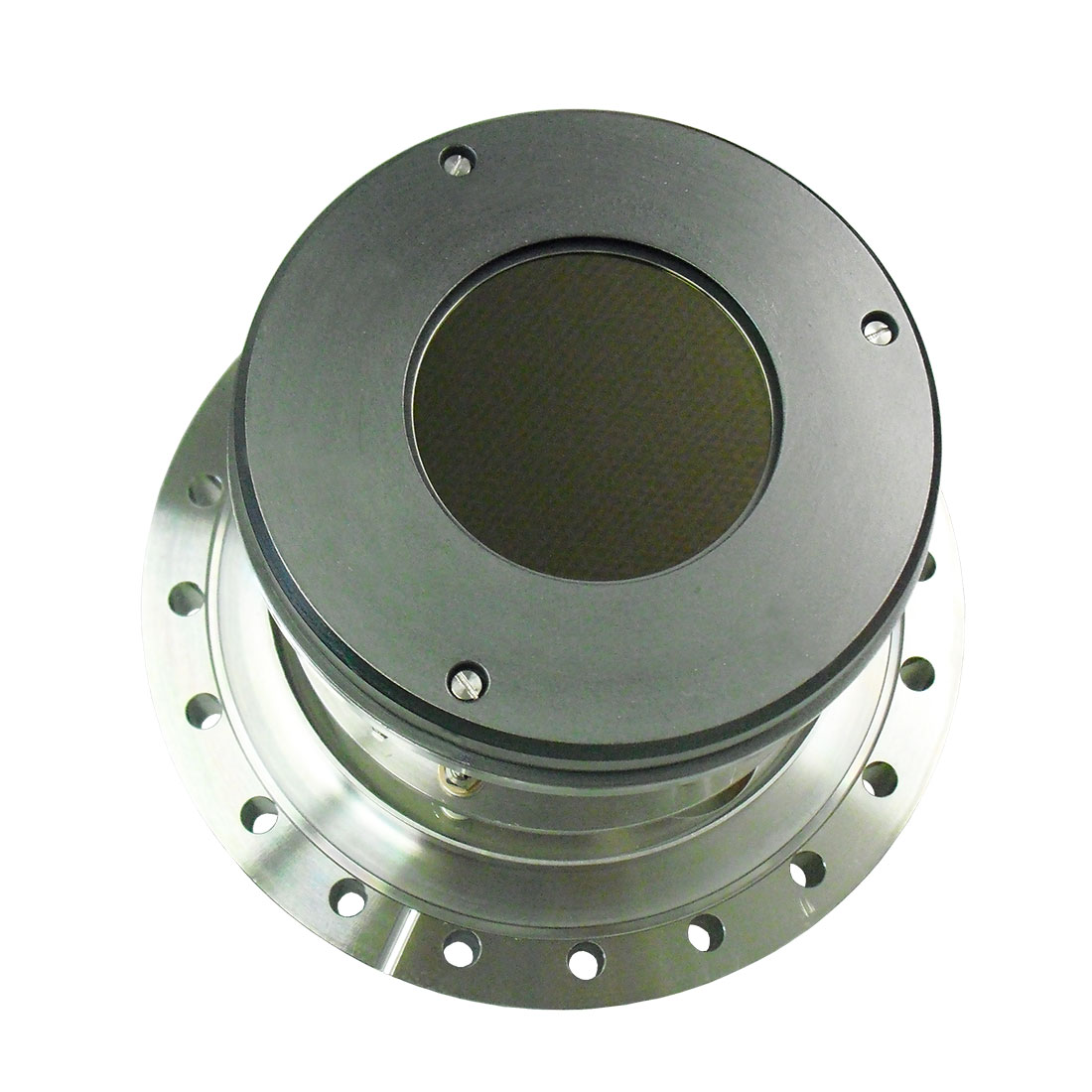
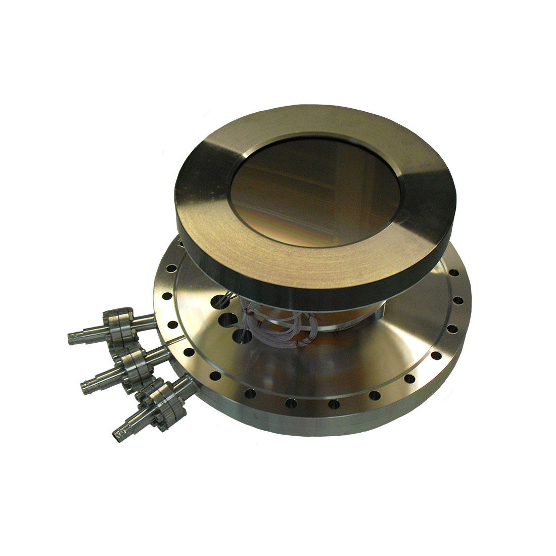
DLD120120 Detector Package
Flange mounted, MCP based single delayline anode detector with 3-fold SHV and 4-fold SMB feedthroughs and cabling for HV supply and pulse decoupling.
- active area: 120mm in diameter
- pixel no.: 2790 x 2790/ 11160 x 11160
- time resolution: <= 130ps (RMS)
- max. random count rate: >= 3Mcps
ELECTRONIC COMPONENTS OF DETECTOR PACKAGES
All detector packages include the following electronic components.

Amplifier Constant Fraction Discriminator Unit
Fast pulse processing unit for delayline detectors.
- direct mounting to the signal feedthrough
- 4x amplifiers
- 4x constant-fraction-discriminator

Time-to-Digital Converter
Time measuring electronics with FPGA based integrated DLD readout logic.
- number of stop inputs: 4
- number of start inputs (reference clock): 1
- measurement range: 0ns – 40µs in start-stop operation
- USB3.0 and 1Gbit ethernet interface for data readout
- inputs/outputs for advanced measurement options

High Voltage Power Supply (optional)
2-channel HV supply for the supply of delayline detectors.
- 2 HV channels for supply of MCP stack and DLD anode
- touch display for manual control
- Ethernet interface for external control
- external reference input for floating operation of HV supply and detector